Show Cover Slide
gpt-4-turbohas translated this article into English.
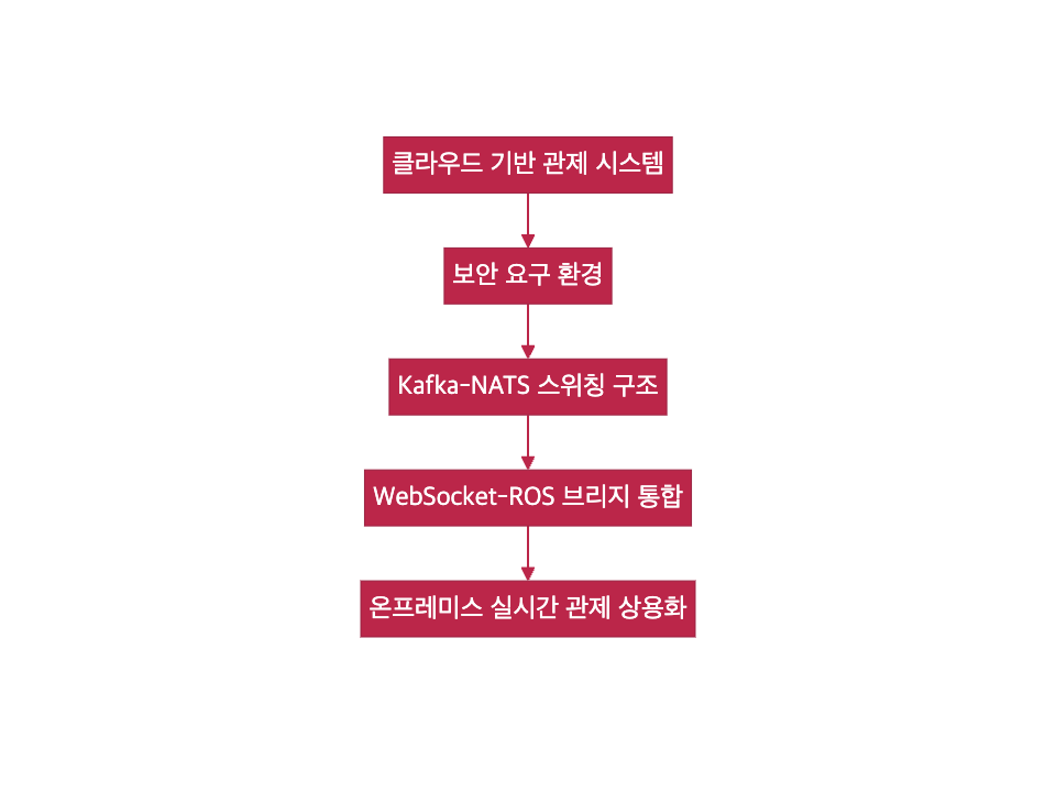
Implementing Cloud Experience on On-Premise with a Robotic Operation Platform Design
This is a design case aimed at implementing a cloud-level development experience and control flow in an on-premise environment.
It is crucial that this design reproduces the entire developer experience in the cloud, not just transferring the technology stack.
Design Philosophy
I believe that the essence of design is not to replicate technology, but to transplant familiar flows into new environments.
In other words, developers and operators should be able to maintain the same development and operational experience regardless of the environment.
This design aimed to create a structure where “the flow itself can be maintained” even in environments where direct use of cloud technologies is not possible.
Problem Definition and Operational Constraints
This project faced the challenge of operating multiple autonomous robots in a secure area within a closed network environment.
While the original system was fully optimized for the cloud, including AWS Lambda and WebSocket, the actual operating environment lacked internet access, imposing the following constraints:
Environmental Constraints
- An independent network environment cut off from external internet
- Inability to directly use cloud services (e.g., AWS MQTT, S3, Lambda, etc.)
- All robots must process messages and visualize data on-site
- Operation of 6 ROS-based robots simultaneously, each requiring independent UI and state control flows
Overall Architecture Structure
The entire system was configured to reflect sensor and state messages from ROS-based robots in real-time on the control server and UI through a NATS-based cluster messaging structure.
Additionally, the serverless event processing flow (Lambda-style) was implemented by transplanting it into a Kubeless-based FaaS structure.
Architecture Diagram
graph TD

subgraph RB1[Robot1]
  ROS[ROS Node]
  AGENT[Agent - YAML & Binary]
  SVC[ROS Update Handler]
  KUBE[Kubeless Function]
  NATS1[NATS - Robot1]
end

RB2[Robot2,...] --> NATS2

subgraph NATS[NATS Cluster]
  NATS1 <--> NATS2[NATS - Robot2,...] <--> NATS_MAIN[NATS - Control Server]
end

ROS --> AGENT --> NATS1
AGENT --> MQTT[AWS IoT MQTT]
NATS --> WS[WebSocket Agent] --> UI[Touch UI / WebView]

MQTT --> SVC --> KUBE
S3[S3 Package Download & Execution] --> SVC
Structure Summary
- Distributed messaging structure using a NATS cluster
- Real-time linking to robot touch UI and control UI via WebSocket Agent
- On-premise serverless deployment flow implemented through Kubeless + S3
- Each robot processes messages individually and simultaneously interacts with cluster messages
Key Design Elements and Implementation
The core of this project was to implement a structure that secures cloud-level real-time responsiveness and operational flexibility in a constrained on-premise environment.
The design was centered around the following five areas:
1. Messaging Processing Structure
- Each robot is equipped with a NATS broker instance for immediate local message processing
- Implementation of distributed message routing with a NATS cluster configuration
- Standardization of ROS messages into a lightweight transmission format via YAML conversion and binary serialization
- Camera frame message processing was included in the design but excluded from actual deployment due to operational constraints
2. UI Integration Structure
- Each robot equipped with touch monitors + WebView UI for on-site control
- WebSocket Agent receives NATS messages for real-time updates
- Similar structure on the control server to provide operator-specific Web UI
- While the UI was dual-structured for on-site and control purposes, the message structure remained consistent
3. Automated Deployment Flow
- Robots receive deployment triggers via AWS IoT MQTT messages
- ROS nodes detect this and call ROS Service to forward deployment requests
- Kubeless Function downloads and executes S3 packages to deploy apps
- Deployment flow of Lambda transplanted to Kubeless, experimentally applied to some features
4. Fault Detection and Monitoring
- State machine-based condition determination logic for fault detection (e.g., speed reduction, sensor non-responsiveness)
- Real-time alerts pushed via MQTT messages
- Metric collection with Prometheus and visualization with Grafana also experimentally implemented
- The primary mode of operation remains manual analysis based on logs
5. Operations and Maintenance Strategy
- All robots registered remotely through a tunneling server
- Operators can directly access and manipulate robots’ internals via tunneling, checking logs and controls
- Manual deployment structure using Helm maintained in parallel
- Kubeless functions managed through CLI or YAML definitions
Through this design, real-time control, remote deployment, and fault response were consistently operational even on-premise.
Technology Choices and Design Rationale
During the design process, considering the environmental constraints that prevent the direct use of existing cloud-based technologies, similarly functional but operable on-premise technology alternatives were evaluated and selected.
Here are the rationales for key technology elements:
| Item | Choice or Transition | Design Rationale |
|---|---|---|
| Kafka → NATS | ✅ Chosen NATS (Excluded Kafka) |
Although Kafka is strong in high throughput, issues with Python client latency and installation complexity were problematic. NATS, being lightweight and stable in Python, is advantageous for real-time applications. |
| Lambda → Kubeless | ✅ Adopted Kubeless (On-premise) |
To replicate Lambda’s serverless architecture on-premise, Kubeless was used. Its Kubernetes-native structure allows for Helm deployment and local execution, making it a viable alternative. |
| MQTT Trigger Automation | ✅ Partially Applied | On-premise robots receive cloud MQTT event messages and operate internally using ROS and Kubeless. Not applied to entire app deployment, experimentally introduced for core features. |
| Prometheus + Grafana | ⚪ Experimentally Applied | Partial nodes configured with Prometheus collectors and tried integrating with Grafana for visualization of message throughput and status metrics. Not essential for operations but considered for scalability and diagnostics. |
| Video Stream Messaging | ❌ Excluded from Operational Deployment | Initially designed NATS-based frame-by-frame video message processing, but not included in actual operations due to bandwidth and real-time issues in a closed network environment. |
By choosing appropriate technology alternatives and redesigning structures, it was possible to maintain the original cloud-based development flow seamlessly even on-premise.
Design Outcomes and Insights
This design was not merely a task of changing technologies but a structural experiment and adjustment process that bridged the gap between the operational environment and technological structure.
The overall results can be summarized from the following three perspectives:
1. Balance between Real-time Responsiveness and Structural Stability
- Designed a high-frequency message processing structure including camera footage, but adjusted traffic flexibly through message filtering, serialization, and namespace configuration considering real environment constraints.
- Consequently, maintained essential real-time responsiveness while securing system stability.
2. Coexistence Strategy of Automation and Manual Operation
- The serverless-based automatic deployment via MQTT → ROS → Kubeless flow was technically valid but some apps were parallelly maintained with manual deployment methods for operational stability.
- Automated flows were restrictively used for repeatable updates, applying a risk distribution strategy.
3. Designing Compromise Points between Design Intentions and Real Constraints
- Powerful cloud technologies like Lambda and Kafka couldn’t be adopted, but structures were replicated using on-premise alternatives like Kubeless and NATS.
- Throughout the process, maintaining consistency of flow and user experience was prioritized as the foremost value.
This project was not simply a combination of robotic systems, messaging structures, and cloud technologies, but a philosophical realization of structural design aimed at maintaining original development experiences within constraints.
Concluding Remarks
This case was about how to design flows, not just a technological issue.
The reason we could implement a development experience and operational structure, seemingly only possible in cloud environments, on-premise with almost the same level of functionality was because “we transplanted experiences, not just replicated technologies.”
Role of the Designer
I see the role of a designer not just as someone who brings in new technologies.
A true designer is someone who designs so that familiar flows can operate in new environments.
That is, although the structure changes, keeping the user experience unchanged is the power of design.
Future Possibilities
This structure will not remain confined to a single project.
- Expansion to other indoor robot services
- Reusability for multi-site integration
- Design basis for cloud-on-premise hybrid structures
Design is always a compromise considering reality, but the way we compromise should not be perceptible to users, which I believe is the structural completeness we should aim for.
Go Home